The avionics mission
I participated on WURocketry's avionics subteam during the 2022–2023 Student Launch project. Our subsystem had three connected responsibilities: trigger drogue and main recovery events without a single electrical point of failure, provide radio tracking for vehicle recovery, and collect onboard measurements that could explain what happened during separation and descent.
SYSTEM ARCHITECTURE
Redundant recovery electronics
2 × EasyMini + independent power and arming → primary and backup ejection chargesSeparate flight computers, batteries, switches, and charge circuits protected the recovery sequence from a single electrical failure. Drogue deployment was staged at apogee and one second later; main deployment was staged at 600 ft and 500 ft AGL.
Vehicle tracking
TeleGPS → 434.55 MHz link → TeleBT + directional ground antennaThe tracking chain sent vehicle coordinates to the ground station so the team could locate the rocket after landing.
Separation diagnostics
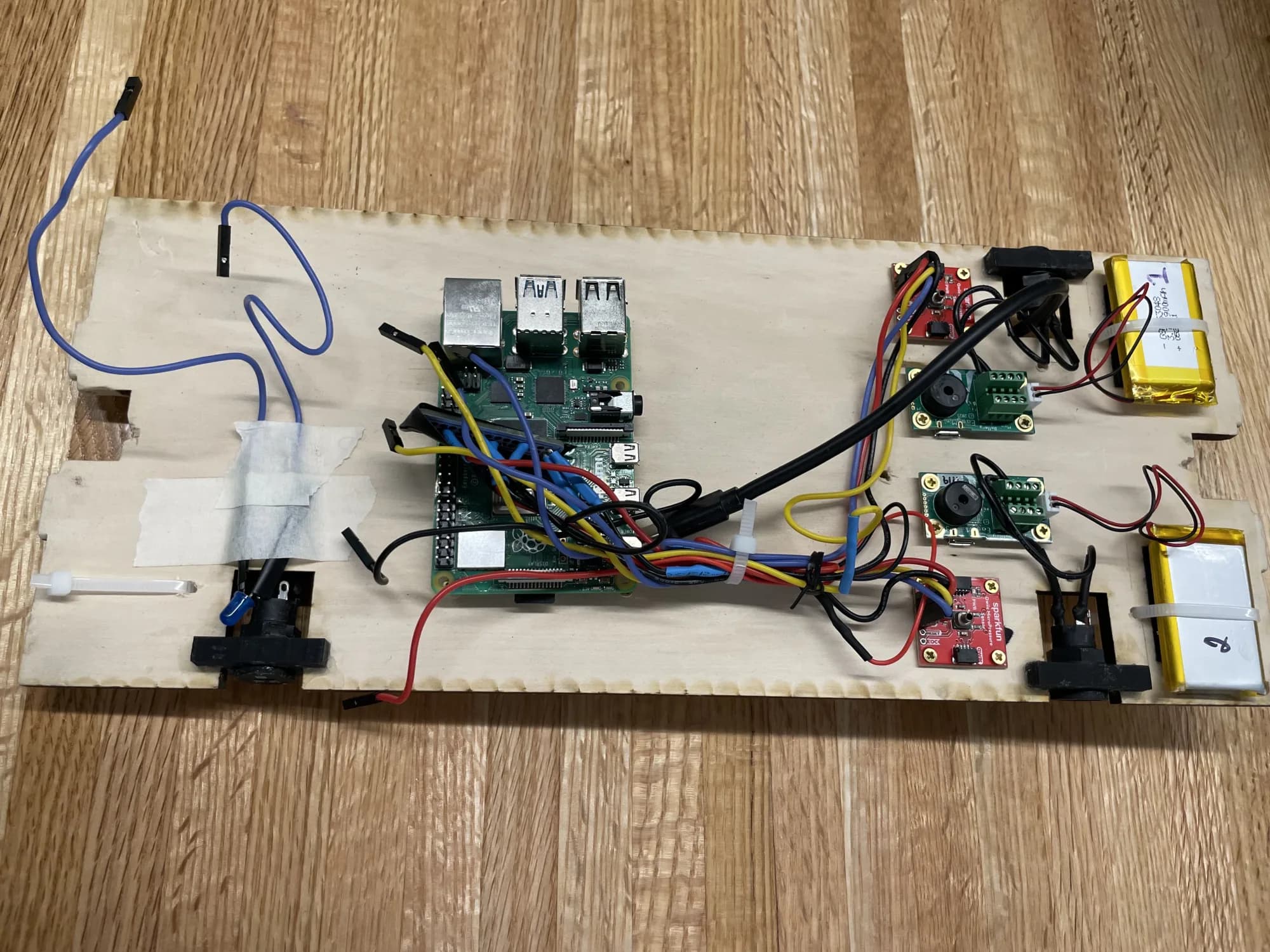
2 × chamber pressure sensor → Raspberry Pi → onboard flight recordPressure sensors sampled the forward and aft separation chambers so deployment events could be checked against the flight-computer record and used to investigate recovery behavior.
How the system came together
- STAGE 01
Package the flight hardware
Integrated recovery computers, tracking hardware, sensing electronics, batteries, switches, and terminal connections across both sides of a removable avionics-bay board.
- STAGE 02
Preserve independent recovery paths
Kept the primary and redundant recovery paths electrically independent, then documented their connections through wiring diagrams, bay schematics, and assembly procedures.
- STAGE 03
Test each measurement chain
Verified GPS communication and accuracy, checked every documented recovery-circuit connection for continuity, and compared primary and redundant altimeter data from a subscale flight.
- STAGE 04
Record separation pressure
Configured a Raspberry Pi to read two pressure sensors over separate I2C buses, write their measurements to a flight log, and capture pressure spikes associated with the two separation events.
- STAGE 05
Read the demonstration flight
Reviewed full-scale flight-computer and chamber-pressure data after the demonstration flight to confirm the recovery sequence and identify the difference between predicted and measured altitude.
Engineering priorities
Redundancy had to remain physical
Calling the design redundant was not enough. The two flight computers needed independent power, arming, wiring, and ejection charges so one failed connection would not disable both recovery paths.
Several systems shared one bay
Recovery electronics, a radio transmitter, pressure sensing, batteries, and structural fasteners competed for limited board space. The layout also had to preserve access for assembly, arming, and preflight checks.
Flight data needed physical interpretation
Altimeter events, acceleration changes, and chamber-pressure spikes described the same flight from different sensors. Reading them together provided stronger evidence of separation than any single plot alone.
What the tests established
- All documented recovery-circuit continuity checks passed before flight.
- The TeleGPS ground test connected to more than ten satellites, and its distance trials remained below the team's three-percent error threshold.
- The primary and redundant flight computers produced closely aligned subscale measurements; the reported mean height difference was 0.533 ft.
- During the full-scale demonstration, both flight computers recorded the drogue and main recovery commands and the two chamber sensors recorded corresponding pressure events.
- The vehicle reached approximately 3,854 ft against a 4,650 ft target and was recovered with no reported damage to the avionics components.
What I took from it
Redundancy only protects a system when the supposedly independent paths do not quietly share power, switching, wiring, or another single failure point.
Ground checks established that each subsystem worked; flight data showed whether recovery, sensing, and the physical vehicle still agreed after integration.
On a large team, clear schematics, procedures, and test records are part of the engineering because they let other people inspect and operate the hardware safely.
Team design reports
Critical Design Review
Searchable team report documenting the mature launch-vehicle design, recovery architecture, avionics hardware, and planned verification work.
Flight Readiness Review
Searchable team report containing the completed avionics design, subsystem tests, demonstration-flight results, and raw flight-data appendices.