The vehicle
We built a Raspberry Pi vehicle that used a blue square as its steering target, regulated wheel speed with feedback, and used ultrasonic range to stop at the end of a hallway. The project brought the camera, sensors, motor electronics, and control software together on one hardware platform.
SYSTEM ARCHITECTURE
Perception and steering
Pi Camera → HSV mask → target centroid → heading error → servo commandThe vision path converted image position into a directional correction rather than attempting full mapping or scene understanding.
Velocity control
Optical wheel signal → MCP3008 → RPS estimate → PI controller → PWM → H-bridge → motorThe control path closed the loop around measured wheel speed and the real drive electronics.
Stopping logic
HC-SR04 → filtered range → stopping condition → motor commandUltrasonic range supplied the final approach and stop condition independently of the camera measurement.
What we built
- STAGE 01
Bring up the electronics
Built and validated the electrical interfaces around the Raspberry Pi, MCP3008 ADC, ultrasonic and inertial sensors, H-bridge motor driver, geared motor, and steering servo.
- STAGE 02
Locate the visual target
Processed Pi Camera frames in OpenCV, isolated the blue target in HSV color space, and converted its image centroid into a steering correction.
- STAGE 03
Measure wheel speed
Measured wheel speed with a photoresistor and black-and-white encoder disk. Transition timing replaced a slower FFT window when the estimate was moved into the feedback loop.
- STAGE 04
Close the velocity loop
Characterized motor speed against PWM duty cycle, then tuned PI control to correct immediate speed error and remaining steady-state bias.
- STAGE 05
Integrate the driving behavior
Combined camera steering, wheel-speed regulation, and ultrasonic stopping through a reusable PiCar interface while coordinating their different update rates.
Key engineering decisions
The interfaces were part of the system
Analog sensing required an external ADC, the 5 V ultrasonic echo needed level reduction for the Raspberry Pi's 3.3 V GPIO, and the motor required an H-bridge. These electrical decisions had to be correct before the software could control anything reliably.
The first speed estimate was too slow for control
FFT analysis confirmed the optical signal's periodicity, but its long sampling window delayed feedback. Counting transitions over a timed buffer produced a lower-latency wheel-speed estimate for the PI controller.
The motor response was not ideal
Static friction, saturation, battery condition, and duty-cycle behavior made a simple linear motor assumption unreliable. Measuring PWM against wheel speed gave the controller a practical operating range.
The evidence defines the scope
The retained work demonstrates a structured target-following task. It does not establish mapping, free-form navigation, dynamic-obstacle avoidance, or quantitative performance across repeated runs.
What worked
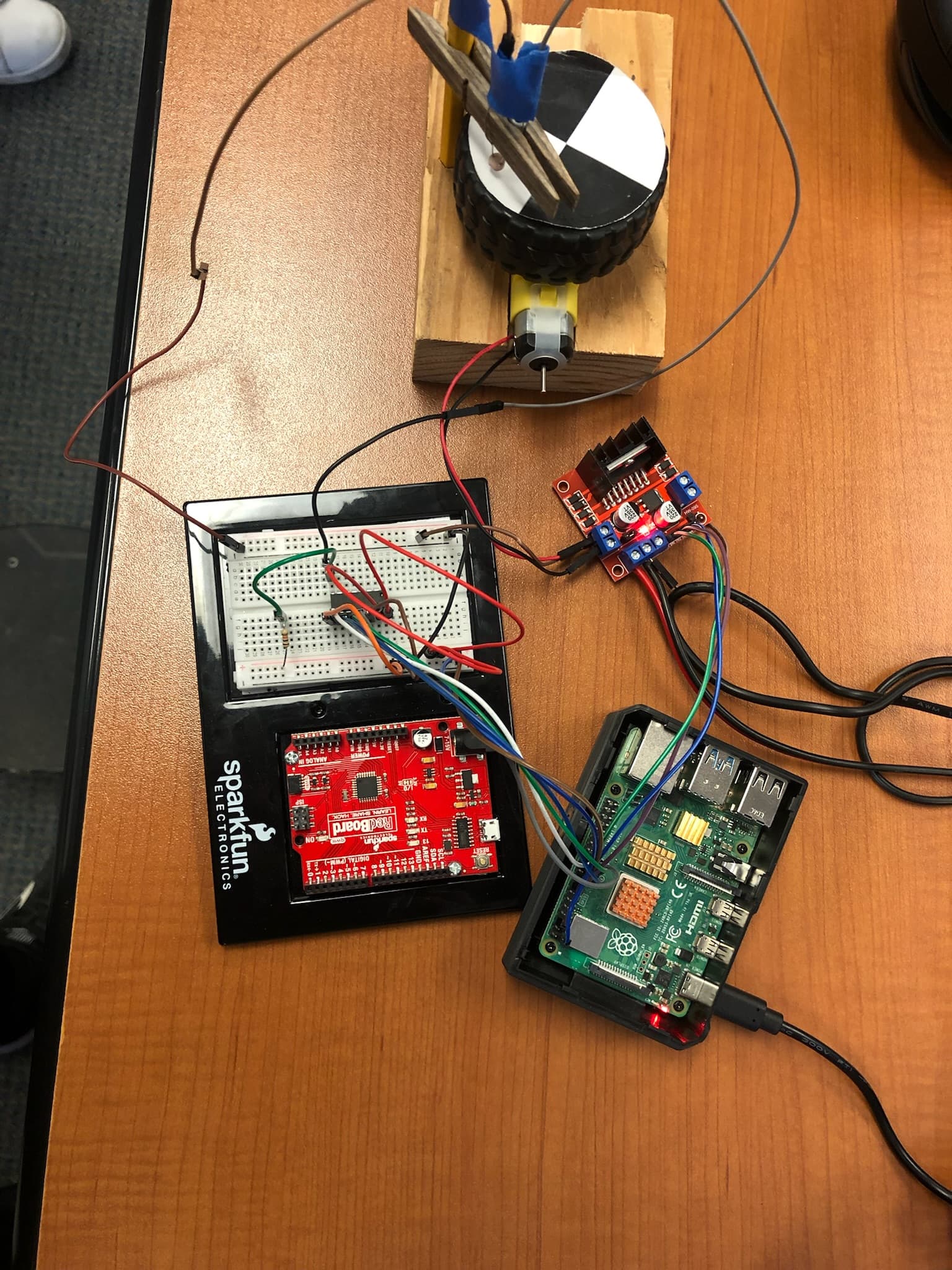
- Bench photographs document the Raspberry Pi, prototyping electronics, H-bridge, geared motor, and optical wheel-speed target used during integration.
- Controller plots preserve two- and six-RPS tests plus the final three-RPS response, where the measured and estimated wheel speeds converge after the initial transient.
- The final implementation combined blue-target centering, closed-loop wheel-speed regulation, and distance-based stopping for the hallway demonstration.
Takeaway
The vehicle worked as an integrated system only after the voltage levels, signal conditioning, timing, sensor quality, and actuator limits were handled explicitly.
Testing each subsystem behind a reusable vehicle interface made it easier to combine vision steering, speed regulation, and stopping without losing track of where a failure originated.