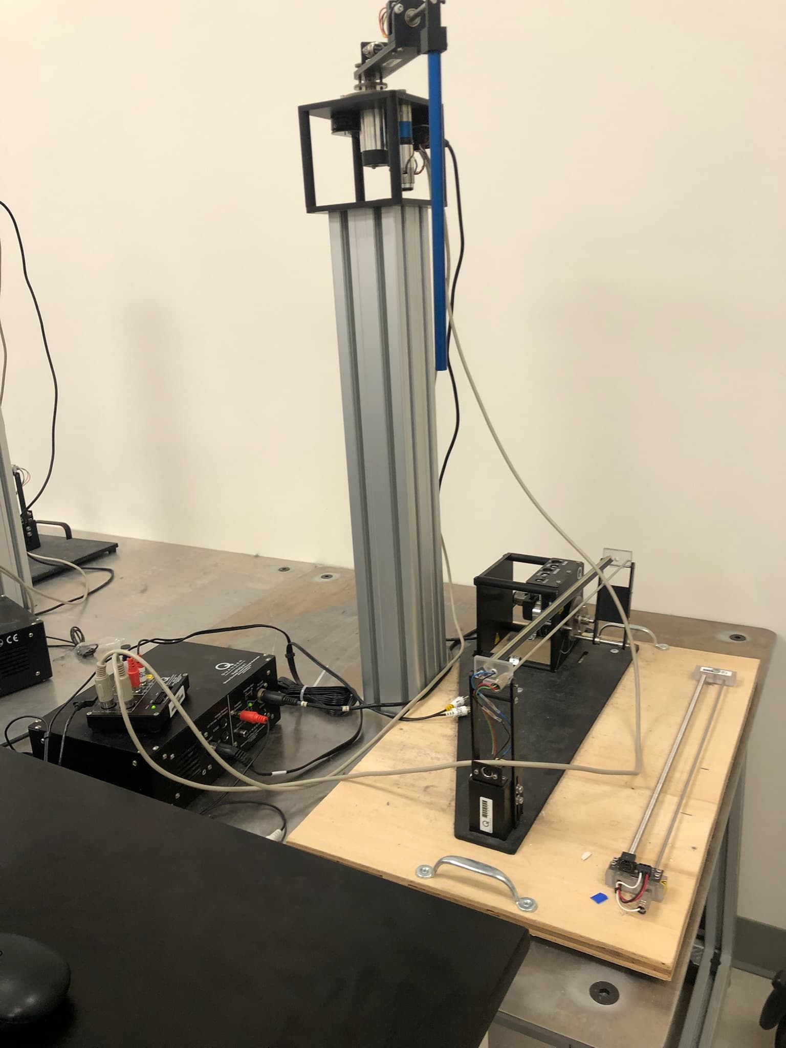
The system
The main project was a rotary inverted pendulum that had to swing upward and balance using one motor. We built the real-time sensing and actuation loop, identified the plant from measured motion, and switched between swing-up and local stabilization. A cart-pendulum simulation remains as a smaller supporting control study.
SYSTEM ARCHITECTURE
Measure and actuate
encoders → QUARC / Simulink → voltage command → amplifier → motorTwo encoders measured the rotary arm and passive link. The real-time model converted counts to angles, estimated velocity, selected a controller, and returned a voltage-limited command to the motor.
Identify the plant
measured motion + voltage → six fitted parameters → nonlinear modelLeast-squares identification captured effective inertia, coupling, gravity, motor behavior, and friction more usefully than nominal dimensions alone.
Switch control modes
swing up → wait → balance → return armA four-mode supervisor wrapped the pendulum angle, checked position and velocity gates, and switched between nonlinear swing-up behavior and local state feedback near upright.
What we built
- STAGE 01
Bring up the hardware loop
Brought up the hardware loop first: verified encoder direction, converted 4,096 counts per revolution to radians, filtered velocity estimates, and limited the motor command to ±10 V.
- STAGE 02
Model and identify the plant
Derived the coupled nonlinear dynamics, then fitted six lumped parameters from measured voltage and motion so the simulation better represented the physical mechanism.
- STAGE 03
Build the operating sequence
Implemented swing-up, wait, balance, and arm-return modes in Simulink, with explicit angle wrapping and transition gates around the upright region.
- STAGE 04
Stabilize the upright position
Linearized the identified model at upright, designed four-state pole-placement feedback, and ran the retained controller at 500 Hz through QUARC.
- STAGE 05
Compare with the cart simulation
Used the cart-pendulum simulation as a supporting study of nonlinear modeling, controllability, and pole-placement stabilization rather than presenting it as a second hardware build.
Key engineering decisions
The model had to match the physical signs
Encoder polarity, angle references, motor direction, friction, and effective inertia all affected whether feedback stabilized the mechanism or reinforced its motion. Hardware traces and identification data exposed those errors more clearly than additional gain tuning would have.
Swing-up and balance needed different controllers
The pendulum could not use the local balance law across its full rotation. Explicit modes and transition gates let the system build energy, recognize the upright capture region, switch to state feedback, and return the arm after an attempt.
The demonstration has a clear limit
The retained hardware clip shows the integrated swing-up and upright-control sequence, but the archive does not include repeated trials or a quantitative long-duration stability test.
What worked
- The final Simulink model closes the complete hardware loop through two encoders, filtered state estimates, four-mode command selection, a ±10 V output limit, and QUARC actuation.
- Six identified parameters brought the simulated and measured motion into qualitative agreement, including their dominant frequency; no numerical fit-error metric was retained.
- The hardware demonstration shows the rotary mechanism moving through swing-up and the upright region under the integrated control sequence.
- The supporting cart simulation holds the pendulum near upright while moving the cart between demonstrated position commands.
Takeaway
The controller only worked when the complete loop was consistent: encoder signs, angle references, filtered velocities, actuator limits, and feedback gains.
Separating swing-up from local balance—and joining them with explicit transition logic—made the nonlinear operating sequence easier to test and debug.
Project documents
Rotary pendulum final presentation
Twelve-slide team presentation covering the hardware, model development, parameter identification, four-mode supervisor, balance controller, and integration problems.
Cart-pendulum simulation report
Six-page supporting simulation report covering the nonlinear cart model, upright linearization, controllability, pole placement, and feedback response.